|
Any competent garage should find this very easy indeed.
You will require a digital multimeter to carry out the adjustments.
Switch ignition on but do not start.

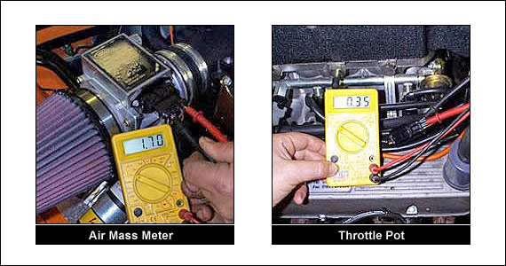
Find the Throttle pot on side of plenum. There are three (3) wires coming from this unit to a multi plug. Do not disconnect. Wire colors are Red, Green, Yellow. Red from volt meter to red wire of pot. Black wire from volt meter to Green of pot. Volts should read .33 to .35 volts if not, loosen the two (2) screws that hold it in position and turn it to get the correct voltage. If you cannot get the correct voltage setting, undo and remove the throttle pot, make the fixing holes elongated and you will be able to get the right voltage.
Please note that the following air flow meter settings should be made when the engine is warm.
The air flow meter wires can be accessed by pulling the rubber boot carefully backwards along the cable. Under here you will find the following wires. Red with Black trace = Sensor ground, Blue with Green trace = air flow signal, Brown with Orange trace = Ignition live 12 volts and Blue with Red trace = CO trim value. A digital multi meter should be used and connected to the sensor ground and CO trim value wires. The values that you are trying to achieve are below and these are adjusted by the screw on the side of the airflow meter.
Air Mass meter setting (non cat)
The voltage reading on the CO value here should be between 1.0 and 1.5. If you have the Tornado ECU chip fitted then 1.5 volts should be aimed for.
Air Mass meter setting (cat)
The best setting for the CO value here is 1.8 volts.
When setting your Throttle potentiometer and Air Mass/flow meter, you should also check the resistance scaling, using an Ohms meter and checking from highest to lowest resistance, smooth scaling is essential for the correct basic workings of all these units.
All High performance and big capacity Hot Wire V8s should consider upgrading to the 4.6 Air Mass Meter as shown above.
|